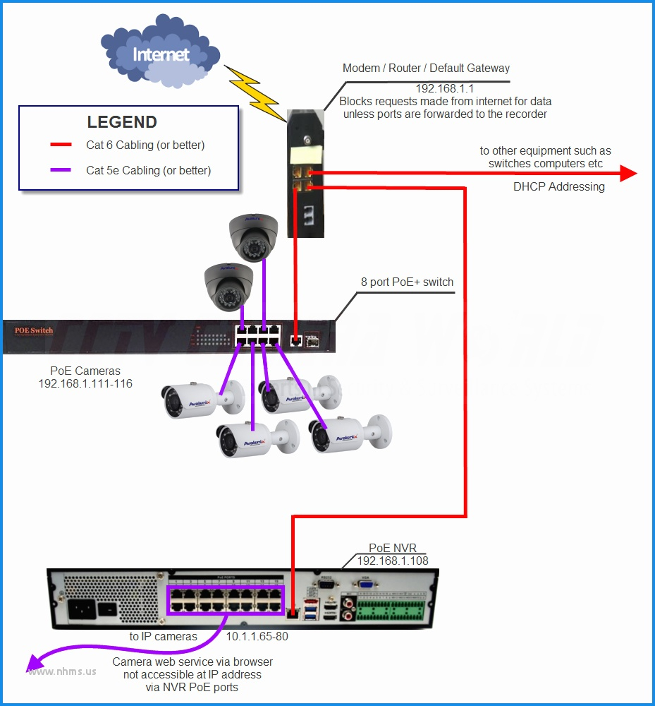

Wiring diagram also provides beneficial recommendations for assignments that might need some extra gear. Lorex cameras come in two basic varieties.ĬCTV closed circuit television and IP Internet protocol or network cameras.
#IP CAMERA PINOUT WIRING DIAGRAM INSTALL#
Lorex 6pin din to rca pinout cable pin converter quick start guide connect analog camera technology shs 4qm user s manual 55ft security extension black how wire my 6 cameras pc install the doorbell zoom technical standard business indoor outdoor color hikvision vs. Wiring diagram wireless security camera closed circuit television ip cctv dvr kit electrical wires cable schematic system png pngwing installation and options cameras. Security Camera Wiring Diagram Schematic. Assortment of ip camera wiring diagram.īest Diagram Of Cctv Camera Cctv Camera Installation Security Cameras For Home Security Camera Installation Wiring Diagram Wireless Security Camera Closed Circuit Television Ip Cctv Dvr Kit Electrical Wires Cable Schematic System Png Pngwing. I think for proper POE it needs to be on both.In some cases youll find a white wire with the whole package. To answer your question, when I punched the wires down for those 2 wires that connect to multiple pins, I just punched them down in both spots. But maybe I'll put another spare connector on this and give it some life in some unused corner of the yard. Chrome/Edge/Firefox all freak out and don't let you enter characters correctly in the login boxes, like it's always backspacing over what you just typed. it's MANY years old and still has the annoying issue where you can only login using IE. It was only recently when I temporarily put it in a spot without any good waterproofing that it quickly corroded the pins in the jack. And this one had been mostly protected during it's useful life. Wouldn't you know, this other one failed with the exact same pin #3 (the yellow-orange wire). just came here to confirm it was still the same). I remembered posting this info and came back to look at the pinouts I'd figured out (after I'd already re-done it. I have another old IPC-HFW4300S I was using for that and it died suddenly. The IPC-HFW4300S I originally fixed is still going strong, although I've basically retired it and just plug it in here and there for interesting things (right now it's watching the local critters that come and go). For the 4+5 and 7+8 pins that are connected, did you short them together with a jumper in your RJ45 jack, or did you just connect one of those pins?ģ years later. I used a punch down tool to add a new RJ45 keystone jack, but my camera is still not working. I have the same coloring scheme as you, and each color maps to the same pin. I have corrosion on the connector, so I cut it off, and probed the 6 wires with my multimeter. Lesson I learned: do it right and save yourself hassles down the road. I assume others might just stuff the wires somewhere else or have it run through a wall, or just leave them exposed (but nicely staples) like I had been doing, which is kind of ugly when I think about it. It's worth it, and you can paint them to blend in so it works out well for me. I started just using waterproof junction boxes for all of my new cameras a few years ago but hadn't refitted the existing ones.

Water found it's way in after some heavy rains. What seemed to cause the pin to break totally this time was a bad o-ring on the waterproof connector, or it wasn't snug enough. This will all go into a waterproof junction box anyway when I put it in it's new location (I had a new camera I hadn't quite figured out where to put yet, so when the Dahua failed I swapped it for that spot). For the separate power connector (black/white/green/red) I just cut them off and taped the leads over to make sure they won't touch anything or each other. I had an RJ45 jack leftover from wiring my house and punched it down, plugged it in, and I'm back in action. The yellow/gray are for the PoE so it's fine they're basically tied together. So, I cut off the connector and got my multimeter out to figure out which of the 6 wires (yeah, just 6, and totally funky colors) went to which pin. Well, one of the pins ended up basically just snapping off (pin #3). at the time I just cleaned it off the best I could (alcohol, a little dab of WD40) and got the copper nice and shiny. I had an issue with it before where water got into the RJ-45 and slightly corroded the pins.

My IPC-HFW4300S (version 1) died last night.


 0 kommentar(er)
